Getting Started with MPASM™/MPLINK™
MPASM™ Assembler
The MPASM™ assembler is a command-line or Windows-based PC application that provides a platform for developing assembly language code for Microchip's PIC® microcontroller (MCU) families. There are two executable versions of the assembler:
The windows version (mpasmwin.exe). Use this version with MPLAB® IDE, in a stand-alone Windows application, or on the command line. This version is available with MPLAB® IDE or with the regular and demo version of the MPLAB® C18 C compiler. This is the recommended version.
The command-line version (mpasm.exe). Use this version on the command line, either from a command shell or directly on the command line. This version is available with the regular and demo version of the MPLAB C18 C compiler. The MPASM™ assembler supports all PIC® MCU devices, as well as memory and KeeLoq© secure data products from Microchip Technology Inc.
The MPASM assembler provides a universal solution for developing assembly code for all of Microchip's PIC MCUs. Notable features include:
MPLAB® IDE Compatibility
Command Line Interface
Windows/Command Shell Interfaces
Rich Directive Language
Flexible Macro Language
ASSEMBLER MIGRATION PATH
Since the MPASM assembler is a universal assembler for all PIC MCU devices, application code developed for the PIC16F877A can be translated into a program for the PIC18F452. This may require changing the few instruction mnemonics that are not the same between the devices (assuming that register and peripheral usage were similar). The rest of the directive and macro language will be the same.
Assembler Template Files
Included with MPLAB IDE are template files for all PIC MCUs. Template files allow you to quick set up a project in MPLAB with a generic file that can be filled in with code as you develop your application. Template files contain the basic structure of a source file, provide some examples for declaring variable storage and for setting device configuration bits.
Assembler Operation
The MPASM assembler can be used in two ways:
To generate absolute code that can be executed directly by a microcontroller.
To generate relocatable code that can be linked with other separately assembled or compiled modules. Relocatable code can not be executed by a microcontroller until it has been linked.
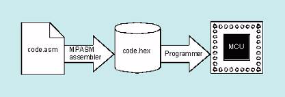
Generating Absolute Code
Absolute code is the default output from the MPASM assembler. This process is shown below.
Simpler Assembler Process
When a source file is assembled in this manner, all variables and routines used in the source file must be defined within that source file, or in files that have been explicitly included by that source file. If assembly proceeds without errors, a hex file will be generated, containing the executable machine code for the target device. This file can then be used with a debugger to test code execution or with a device programmer to program the microcontroller.
Generating Relocatable Code
The MPASM assembler also has the ability to generate a relocatable object module that can be linked with other modules using Microchip's MPLINK linker to form the final executable code. This method is very useful for creating reusable modules.
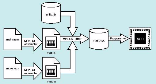
Link Process
Related modules can be grouped and stored together in a library using Microchip's MPLIB librarian. Required libraries can be specified at link time, and only the routines that are needed will be included in the final executable.
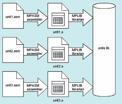
Library Build Process
Source Code
Assembly is a programming language you may use to develop the source code for your application. The source code file may be created using any ASCII text file editor or using MPLAB’s Programmer’s Editor. Your source code should conform to the following basic guidelines. Each line of the source file may contain up to four types of information:
Labels – “tags” given to locations in source code
Mnemonics – short names that are given for each machine instruction
Operands – most mnemonics operate on operands, such as registers, labels or numbers
Directives – special instructions to the assembler
Macros – short cuts for defining commonly used assembly routines
Comments – user notations to the code
The order and position of these are important. For ease of debugging, it is recommended that labels start in column one and mnemonics start in column two or beyond. Operands follow the mnemonic. Comments may follow the operands, mnemonics or labels, and can start in any column. The maximum column width is 255 characters. Comments can also be on a line by themselves
White space or a colon must separate the label and the mnemonic, and white space must separate the mnemonic and the operand(s). Multiple operands must be separated by commas. “White space” is one or more spaces or tabs. White space is used to separate pieces of a source line. White space should be used to make your code easier to read. Unless within character constants, any white space means the same as exactly one space. Files associated with MPASM are listed here:
Source Code (.asm) Default source file extension input to assembler.
Include File (.inc) Include (header) file.
Listing File (.lst) Default output extension for listing files generated by assembler.
Error File (.err) Output extension from assembler for error files.
Hex File Formats (.hex, .hxl, .hxh) Output extension from assembler for hex files.
Cross Reference File (.xrf) Output extension from assembler for cross reference files.
Symbol and Debug File (.cod) Output extension for the symbol and debug file. For absolute code, this file will be generated by the assembler. For relocatable code, this file and a .coff file will be generated by the MPLINK linker.
Object File (.o) Output extension from assembler for object files.
Example Absolute MPASM Assembler Source Code
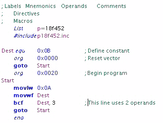
MPASM Assembler Source Code Example
Labels
A label is used to represent a line or group of code, or a constant value. It is needed for branching instructions. Labels should start in column 1. They may be followed by a colon (:), space, tab or the end of line. Labels must begin with an alpha character or an under bar (_) and may contain alphanumeric characters, the under bar and the question mark.
Labels must not:
begin with two leading underscores, e.g., __temp.
begin with a leading underscore and number, e.g., _2NDLOOP.
be an assembler reserved word (mnemonic, directive, etc.).
Labels may be up to 32 characters long. By default they are case sensitive, but case sensitivity may be overridden by a command-line option (/c). If a colon is used when defining a label, it is treated as a label operator and not part of the label itself.
Mnemonics, Directives and Macros
Mnemonics tell the assembler what machine instructions to assemble. For example, addition (add), branches (goto) or moves (movwf). Unlike labels that you create yourself, mnemonics are provided by the assembly language. Mnemonics are not case sensitive.
Directives are assembler commands that appear in the source code but are not usually translated directly into opcodes. They are used to control the assembler: its input, output, and data allocation. Directives are not case sensitive.
Macros are user defined sets of instructions and directives that will be evaluated in-line with the assembler source code whenever the macro is invoked.
Assembler instruction mnemonics, directives and macro calls should begin in column two or greater. If there is a label on the same line, instructions must be separated from that label by a colon, or by one or more spaces or tabs.
Operands
Operands give information to the instruction on the data that should be used and the storage location for the instruction. Operands must be separated from mnemonics by one or more spaces, or tabs. Multiple operands must be separated by commas.
Comments
Comments are text explaining the operation of a line or lines of code. The MPASM assembler treats anything after a semicolon as a comment. All characters following the semicolon are ignored through the end of the line. String constants containing a semicolon are allowed and are not confused with comments.
Include File
An assembler include, or header, file is any file containing valid assembly code. Usually, the file contains device-specific register and bit assignments. This file may be “included” in the code so that it may be reused by many programs. As an example, to add the standard header file for the PIC18F452 device to your assembly code, use:
#include p18f452.inc
Standard header files are located in:
C:\Program Files\Microchip\MPASM Suite
Listing File
An MPASM assembler listing file provides a mapping of source code to object code. It also provides a list of symbol values, memory usage information, and the number of errors, warnings and messages generated. This file may be viewed in MPLAB IDE by:
selecting File>Open to launch the Open dialog
selecting “List files (*.lst)” from the “Files of type” drop-down list
locating the desired list file
clicking on the list file name
clicking Open
Both the MPASM assembler and the MPLINK linker can generate listing files. To prevent assembler list file generation, use the /l- option or use with MPLINK linker
(The linker list file overwrites the assembler list file.) Set the size of tabs in the list file using the /t option.
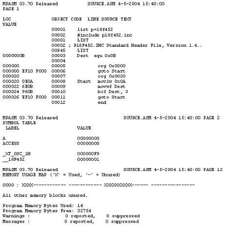
Example: Absolute MPASM Assembler Listing File
The product name and version, the assembly date and time, and the page number appear at the top of every page.
The first column contains the base address in memory where the code will be placed.
The second column displays the 32-bit value of any symbols created with the set, equ, variable, constant, or cblock directives.
The third column is reserved for the machine instruction. This is the code that will be executed by the PIC MCU.
The fourth column lists the associated source file line number for this line. The remainder of the line is reserved for the source code line that generated the machine code.
Errors, warnings, and messages are embedded between the source lines and pertain to the following source line. Also, there is a summary at the end of the listing. The symbol table lists all symbols defined in the program.
The memory usage map gives a graphical representation of memory usage. 'X' marks a used location and '-' marks memory that is not used by this object. The map also displays program memory usage. The memory map is not printed if an object file is generated.
Although the assembler can be used in either absolute or relocatable mode, it is preferred to use the relocatable mode for a these reasons:
Code libraries can be used by multiple applications.
Large source code is more easily maintained in smaller, modular files.
The linker outputs COFF (common object file format) files which provide more robust debugging.
Writing source code that will be assembled to an object module is slightly different from writing code used to generate an executable (hex) file directly. MPASM assembler routines designed for absolute address assembly will require minor modifications to compile correctly into relocatable object modules.
Program Memory
Program memory code must be organized into a logical code section. To do this, the code must be preceded by a code section declaration to make it relocatable.
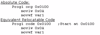
If more than one code section is defined in a source file, each section must have a unique name. If the name is not specified, it will be given the default name .code.
Each program memory section must be contiguous within a single source file. A section may not be broken into pieces within a singe source file.
The physical address of the code can be fixed by supplying the optional address parameter of the code directive. Situations where this might be necessary are:
Specifying reset and interrupt vectors
Ensuring that a code segment does not overlap page boundaries
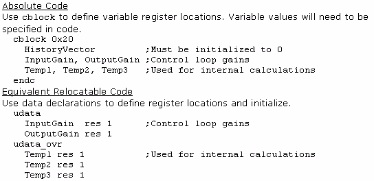
Ram Allocation
RAM space must be allocated in a data section. Five types of data sections are available:
Note: The ability to use access, overlaid or shared data varies by device. Consult your device data sheet for more information.
udata - Uninitialized data. This is the most common type of data section. Locations reserved in this section are not initialized and can be accessed only by the labels defined in this section or by indirect accesses.
udata_acs - Uninitialized access data. This data section is used for variables that will be placed in access RAM of PIC18 devices. Access RAM is used as quick data access for specified instructions.
udata_ovr - Uninitialized overlaid data. This data section is used for variables that can be declared at the same address as other variables in the same module or in other linked modules. A typical use of this section is for temporary variables.
udata_shr - Uninitialized shared data. This data section is used for variables that will be placed in RAM of PIC12/16 devices that is unbanked or shared across all banks.
idata - Initialized data. The linker will generate a lookup table that can be used to initialize the variables in this section to the specified values. When linked with MPLAB C18 code, these locations will be initialized during execution of the startup code. The locations reserved by this section can be accessed only by the labels defined in this section or by indirect accesses. This directive is only useful when using MPLAB C18 compiler, because special initialization code, included with the compiler, is required.
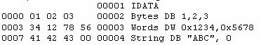
Example: RAM Allocation
RAM Allocation Example
If necessary, the location of the section may be fixed in memory by supplying the optional address parameter. If more than one of each section type is specified, each section must have a unique name. If a name is not provided, the default section names are: .idata, .udata, .udata_acs, .udata_shr, and .udata_ovr.When defining initialized data in an idata section, the directives db, dw, and data can be used. db will define successive bytes of data memory. dw and data will define successive words of data memory in low-byte/high-byte order. The following example shows how data will be initialized.
Example: Relocatable Code listing
Relocatable Code Listing
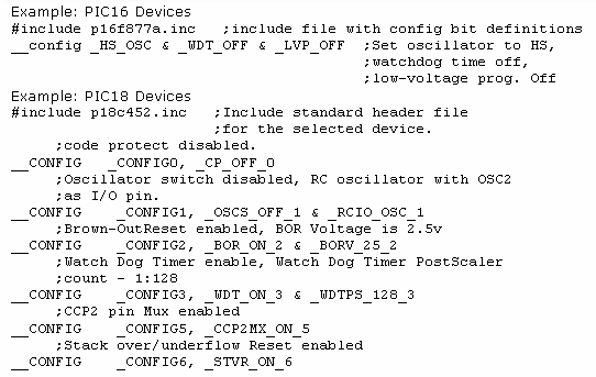
Processor Configuration Bits
Processor configuration bits determine the various modes that the processor operate. These bits determine whether a watchdog timer is enabled and what its period will be, the type of oscillator used to clock the microcontroller, and the configuration of pins that can be used for various alternative purposes.
The assembler handles this with the __config directive. This directive is placed in source code so that, when the code is assembled into a hex file, the configuration values are preset to desired values in your application. This is useful when giving your files to a third-party programming house, as this helps insure the device is configured correctly when programmed.
Place configuration bit assignments at the beginning of your code. Use the configuration options (names) in the standard include (*.inc) file. These names can be bitwise ANDed together using & to declare multiple configuration bits.
Note: config is preceded by two underline characters.
Accessing Labels from Other Modules
Labels that are defined in one module for use in other modules must be exported using the global directive. Modules that use these labels must use the extern directive to declare the existence of these labels. An example of using the global and extern directives is shown below.
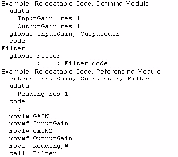
Relocatable Code, Defining Module
Paging and Banking Issues
In many cases, RAM allocation will span multiple banks, and executable code will span multiple pages. In these cases, it is necessary to perform proper bank and page set-up to properly access the labels. However, since the absolute addresses of these variable and address labels may not be known at assembly time, it is not always possible to place the proper code in the source file. For these situations, two new directives, banksel and pagesel have been added. These directives instruct the linker to generate the correct bank or page selecting code for a specified label. An example of how code should be converted is shown below.
Note that the PIC18 family does not use pagesel (it will be ignored), and often times the PIC18 access register area can be used without using banksel.
Example: Hard coding banking and paging
Use indirect addressing (FSR) and the Status register for banking and paging, respectively.
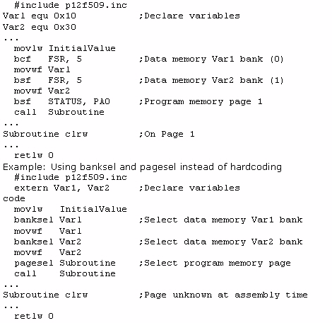
Code Example
For full details on the instruction sets, MPASM and MPLINK directives and operations see MPLAB’s on-line help or these documents:
MPASM/MPLINK User’s Guide
MPASM/MPLINK PIC Quick Chart
Informacion disponible directamente en la pagina del fabricante:
http://www.microchip.com/developmenttools/getting_started/gs_mplab2.aspx